Turn a Face Into a Drawing Plane Fusion
Flipping, Mirroring, Rotating and Arrays
With SketchUp'southward flipping and rotating tools, your geometry becomes as nimble equally an acrobatic troupe. The Flip Along control enables geometry to backflip 180 degrees along whatever axis. With the Rotate tool, your geometry can spin and fold like a professional gymnast.
Table of Contents
- Flipping geometry along an axis
- Rotating geometry at an angle
- Corner Inference Grips
- Folding geometry forth an axis
Flipping geometry forth an axis
To flip your geometry, follow these steps:
- With the Select tool (
 ), select the geometry you want to flip.
 - Context-click your selection and select Flip Along.
- In the submenu, select an axis.
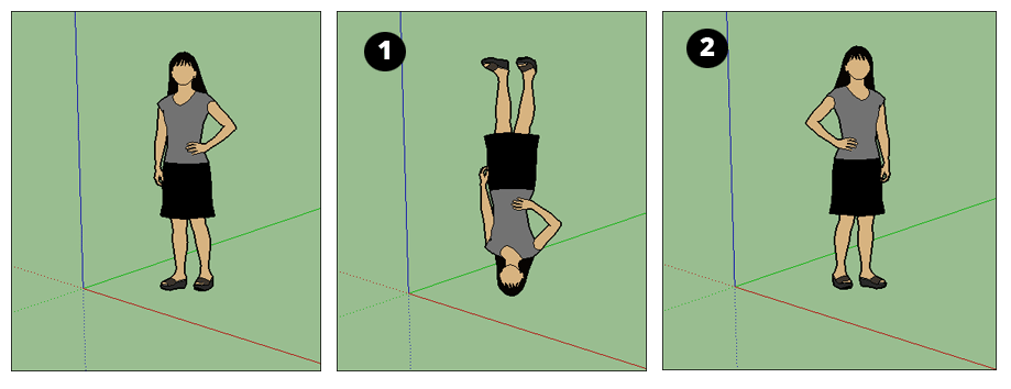
In the effigy, Sophie demonstrates the results of flipping along the blue axis (one) or the cerise axis (2).
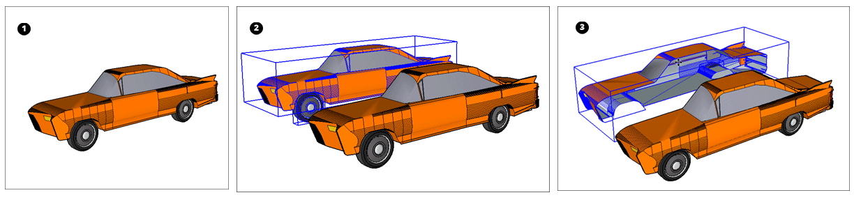
Tip: By combining the Copy and Flip Along commands, y'all can mirror geometry. When you're modeling objects like cars (or anything that's the aforementioned on both sides), mirroring enables you to create one half of a model (1), re-create it (two), and so flip the copy (3) to create a mirror that completes the model, as shown in the following effigy. See Selecting Geometry for tips on making complex selections.
Rotating geometry at an bending
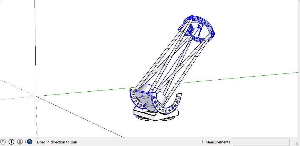
With the Rotate tool, yous tin rotate geometry at any angle. For example, say you want to rotate this telescope so that it points at a unlike angle or a different part of the sky.
Hither's how to employ the Rotate tool to spin geometry around:
- With the Select tool (), select the geometry you want to rotate. Here, the geometry that points the telescope into the heaven is selected, but not the base, which needs to stay on the ground.
- Select the Rotate tool (
 ). The Rotate tool's protractor-shaped cursor appears
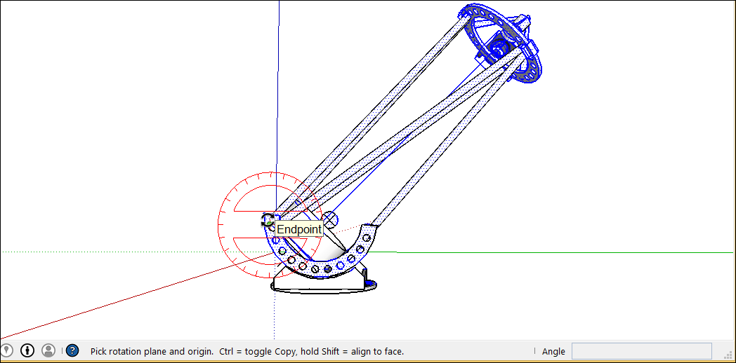
 - Motility the cursor around until information technology's on the airplane you want to apply for your rotation. To lock the plane, printing the Shift key until you click to set the angle's vertex. When your plane is perpendicular to an axis, the cursor turns blood-red, greenish, or blue, respectively, as shown in the figure.
Tip: When yous printing and concord the Shift key to constrain the plane of rotation, yous can press Alt (Microsoft Windows> or Control (OS X) to free the protractor from the inferenced plane. The angle of the protractor will remain the angle of the original plane, but now you tin can move the protractor to inference other geometry.
Tip: In this example, inferring from a face up that'due south on the same plane as the desired rotation is the easiest fashion to find the right plane. Hold downward the whorl wheel of your iii-button mouse to temporarily switch to the Orbit tool (
 ) and find a proficient view of your desired plane. Come across Viewing a Model for details almost viewing options.
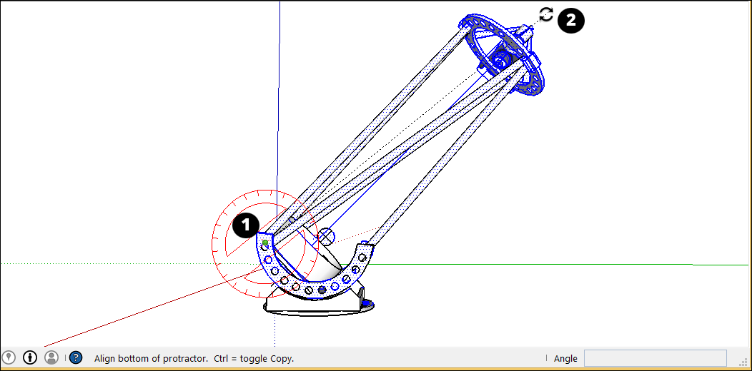
 - Click to set your angle's vertex (Callout i in the post-obit figure).
- With the circular arrow cursor, click to set offset bespeak of your rotation angle. In this example, the starting betoken (Callout 2 in the following effigy) is parallel to the current angle of the telescope.
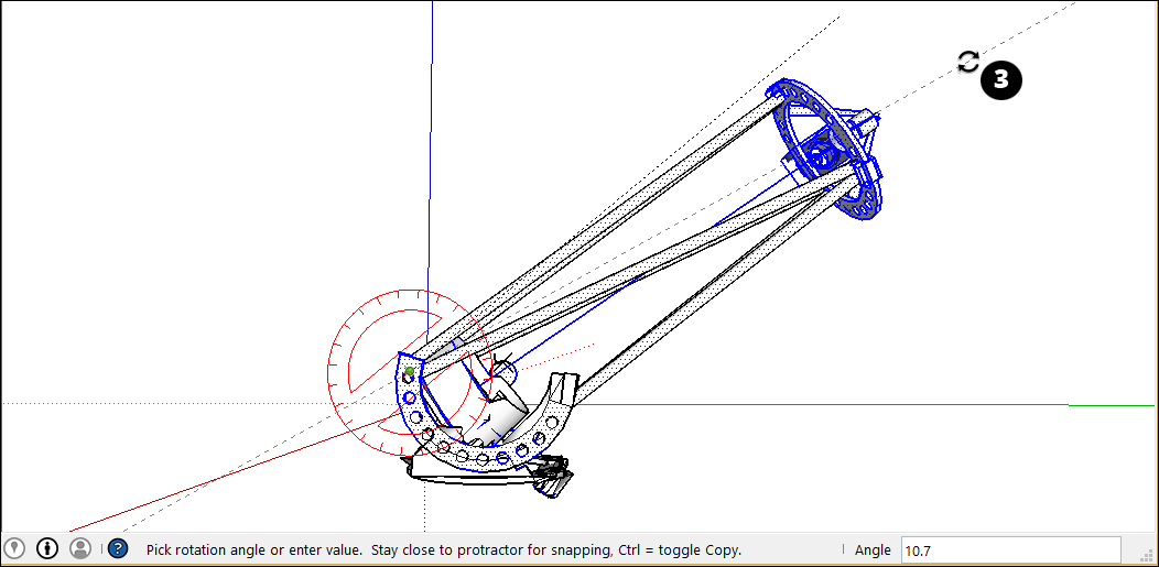
- Move the cursor in the management of your rotation and click to complete the rotation angle. In the figure, the circular arrow cursor is positioned where you might click to complete the rotation (Callout 3). Notice that the Measurements box indicates the angle.
- (Optional) Blazon a precise angular rotation or slope value and and so press Enter. The following table outlines how to specify each value. Negative values move the bending rotation in a counter-clockwise direction.
| To Specify This . . . | Type This | Instance |
|---|---|---|
| An exact angle in degrees | A decimal value | Blazon 34.1 to rotate by an verbal 34.ane caste angle. |
| A new angle as a slope | The ii values separated by a colon | Type eight:12 for a gradient of 8 over 12. |
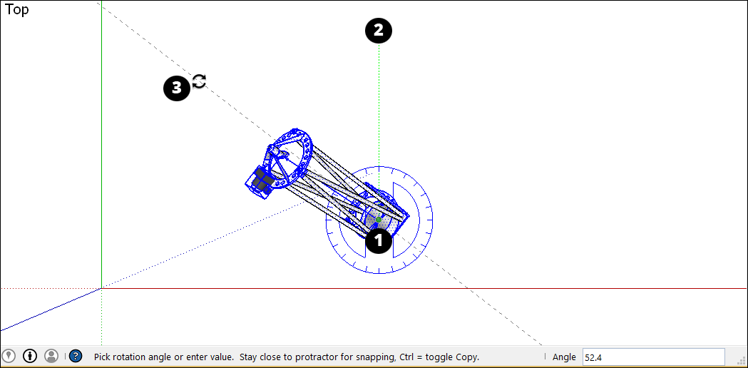
Here's another example to help you understand how to achieve your desired rotation angle. Imagine you lot need to rotate the whole telescope to a unlike part of the heaven (northwest, say, instead of due due north). Start by selecting the whole telescope and then select Camera > Standard Views > Superlative to run into the telescope from above. (Viewing a Model explains SketchUp'due south viewing options.) With the Rotate tool selected, you lot and then lock the protractor cursor in the blue direction and click the top to fix the bending'south vertex (Callout 1). Click to start your angle at due Northward (2) and then click again to complete the angle at your desired Northwest direction (3).
In the following video, watch the Rotate tool in action, where you see how to rotate clock hands and open a vault door, fold a SketchUp face into a paper plane, and more.
Corner Inference Grips
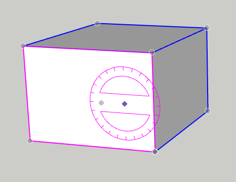
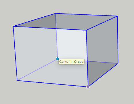
When selecting or hovering over a component/group, you'll find in that location are inference icons. These reference icons are presented differently depending on the geometry and action being performed. In the prototype below, the corners of the component/group'south bounding box to help yous better rotate the component/group. The component/grouping grips are represented as a gray dot at every corner of the box. You can grab and rotate the object using these grips.
When yous move your cursor over a corner which is obscured by other geometry, the gray dot volition become blue and your component will display as transparent to help y'all see the obscured corner and geometry behind for placement.
You can cycle through bachelor grips, Object Center, Context Edge Centre and Context Edge Corner by finding your first grip, then toggling through them using Command on Mac or Alt on Windows.
Folding geometry along an centrality
SketchUp geometry is so flexible, you lot tin can fold it like newspaper. Follow these steps:
- With the Select tool (), select the geometry you want to fold.
- Select the Rotate tool ().
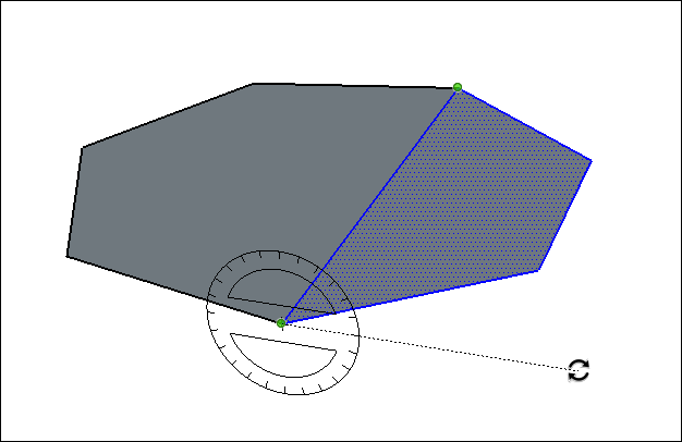
- With the Rotate tool's protractor-shaped cursor, click and elevate from one endpoint on the fold line to the other endpoint. Release the mouse button when yous're done. In this example, the line that bisects the polygon is the fold line.
- Click at the starting point of the rotation. In the figure, the circular arrows cursor is where the rotation begins.
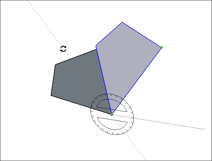
- Move the mouse to rotate. If bending snaps are active under preferences, movements close to the protractor issue in angle snaps, whereas those further away allow free rotation. Also, as you move the cursor, notice that the angle degrees of rotation announced in the Measurements box.
- Click at the catastrophe bespeak to complete the rotation. The post-obit figure shows the rotation'southward catastrophe signal and the dynamic preview of the folded polygon.
- (Optional) Type a precise athwart rotation or slope value and then printing Enter. See the earlier table for details about how to specify each value. Negative values fold the geometry in a counter-clockwise direction.
garrisbacticeived.blogspot.com
Source: https://help.sketchup.com/en/sketchup/flipping-mirroring-rotating-and-arrays
0 Response to "Turn a Face Into a Drawing Plane Fusion"
Post a Comment